<?xml version="1.0" encoding="utf-8"?><feed xmlns="http://www.w3.org/2005/Atom" ><generator uri="https://jekyllrb.com/" version="4.4.1">Jekyll</generator><link href="https://mcsgroi.xyz/feed.xml" rel="self" type="application/atom+xml" /><link href="https://mcsgroi.xyz/" rel="alternate" type="text/html" /><updated>2026-06-04T20:20:01-05:00</updated><id>https://mcsgroi.xyz/feed.xml</id><title type="html">Michael Sgroi</title><subtitle>Technology Leader | Software Engineer | CIS Professor</subtitle><author><name>Michael Sgroi</name></author><entry><title type="html">Custom Vacuum Former</title><link href="https://mcsgroi.xyz/2021/09/26/custom-vacuum-former/" rel="alternate" type="text/html" title="Custom Vacuum Former" /><published>2021-09-26T23:52:45-05:00</published><updated>2021-09-26T23:52:45-05:00</updated><id>https://mcsgroi.xyz/2021/09/26/custom-vacuum-former</id><content type="html" xml:base="https://mcsgroi.xyz/2021/09/26/custom-vacuum-former/"><![CDATA[<p>It should be evident already from previous posts, but I do a lot of 3D printer work in my free time. Recently though, I have been trying to expand my plastics works possibilities. I’ve contemplated making a vacuum former or an injection molder. Naturally, building a vacuum former is much simpler than an injection molder so I decided to start with that. I watched quite a few YouTube videos in preparation for this build. Most of my decisions were influenced by <a href="https://www.youtube.com/watch?v=9ynFpxokWlM">this build video</a> although I definitely took a different approach to some of the decisions.</p>

<p>
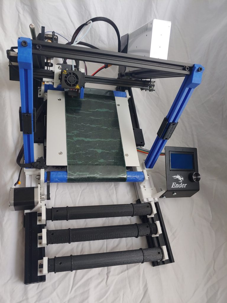
I ended up starting by purchasing a ceiling mount space heater. I looked over the one in his video and thought it was perfect for this, but it seemed a bit overpriced so I did some more searching. I found out that Menards (for anyone outside of the midwest US, that’s a local hardware store chain) carries a model that is identical and just rebranded for less than half the currently listed price of the one included in that video. Now that I had that, I took some measurements and started with the base box.</p>

<div class="image-grid">
  <figure>
    <img src="/assets/images/wp/P_20210921_091352-1024x768.jpg" alt="" />
  </figure>
  <figure>
    <img src="/assets/images/wp/P_20210921_091331-1024x768.jpg" alt="" />
  </figure>
  <figure>
    <img src="/assets/images/wp/P_20210924_191029-768x1024.jpg" alt="" />
  </figure>
  <figure>
    <img src="/assets/images/wp/P_20210924_190958-768x1024.jpg" alt="" />
  </figure>
  <figure>
    <img src="/assets/images/wp/P_20210924_190127-768x1024.jpg" alt="" />
  </figure>
</div>

<p>
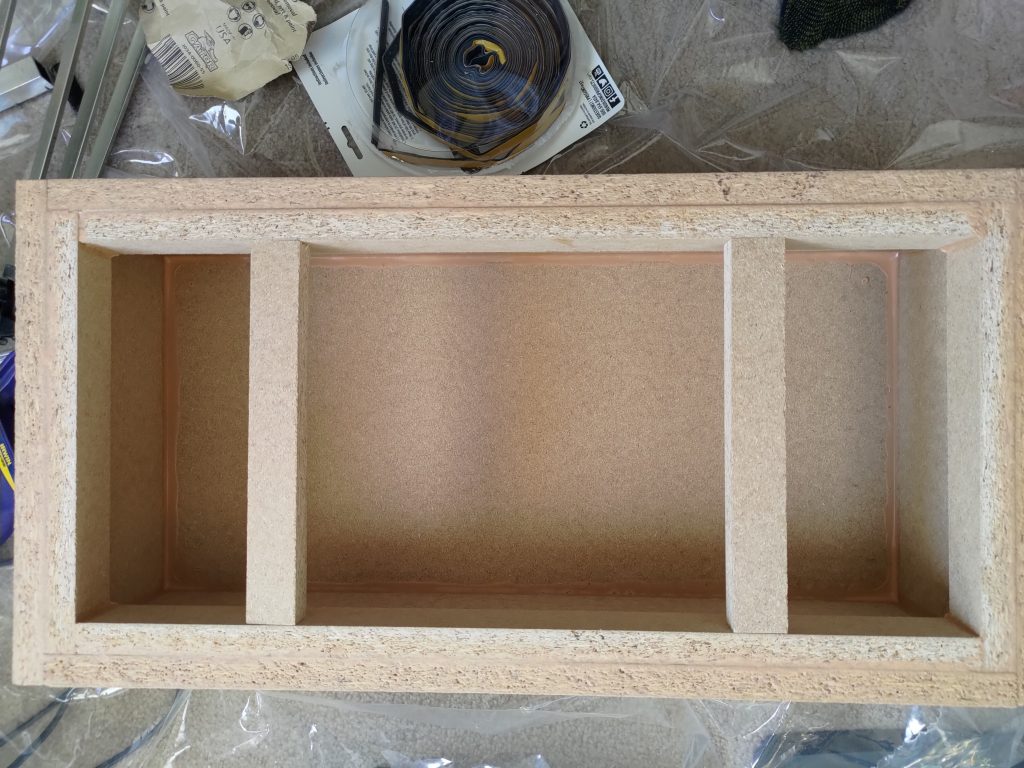
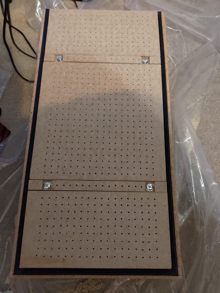
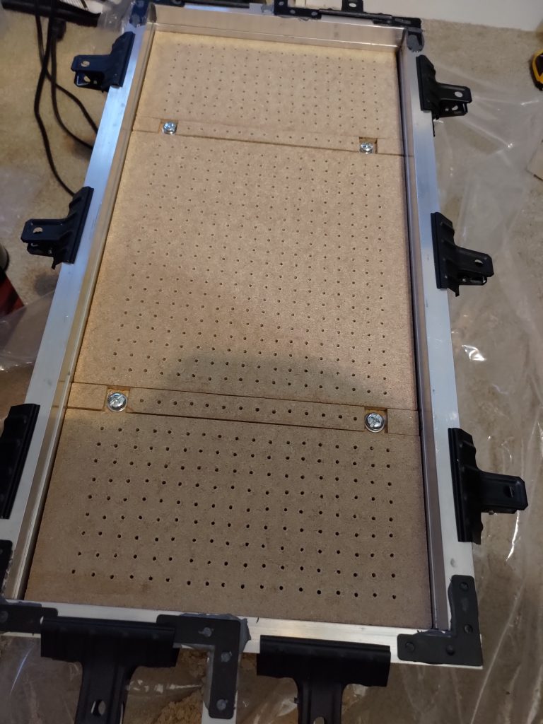
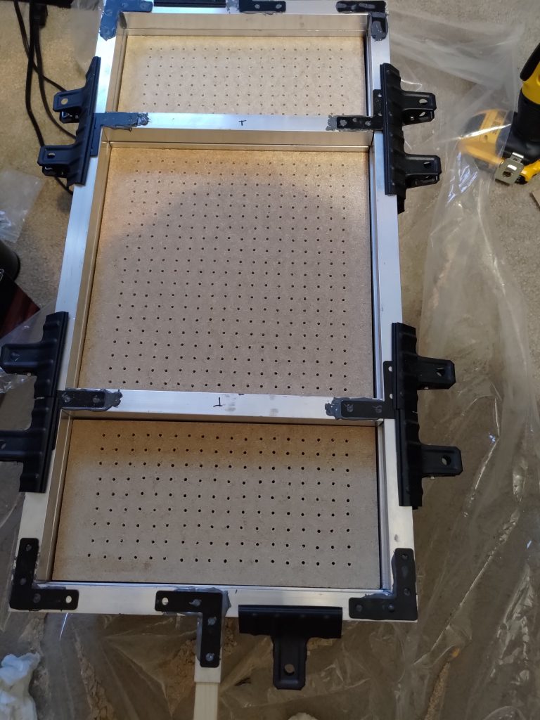
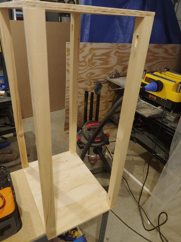
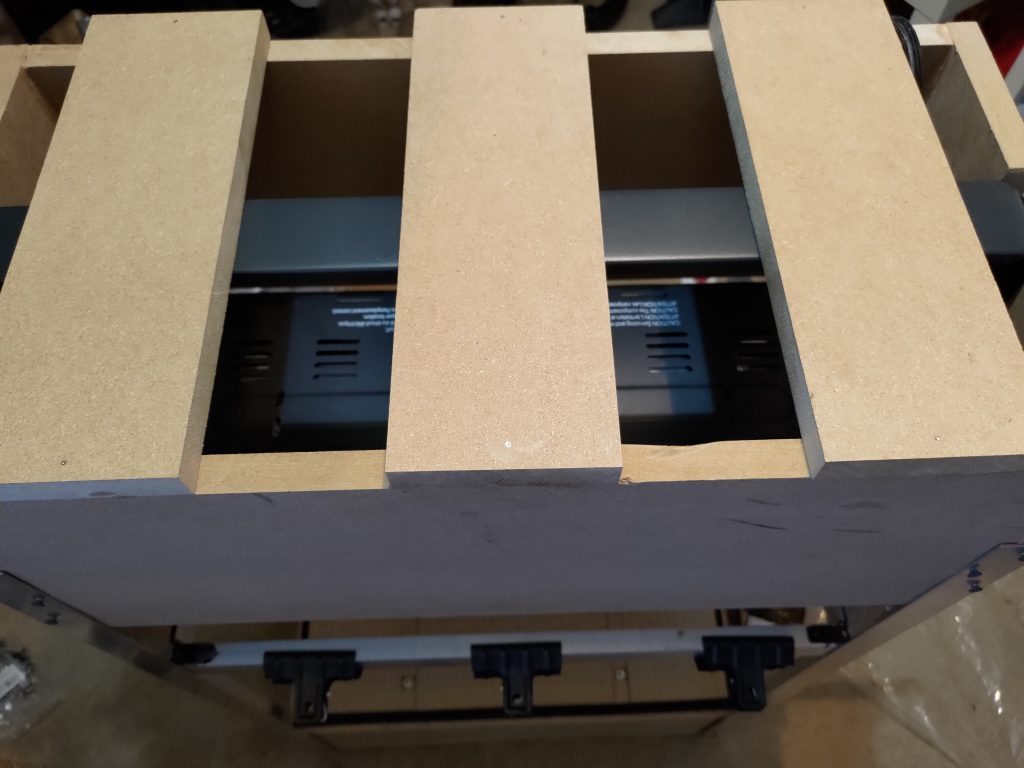
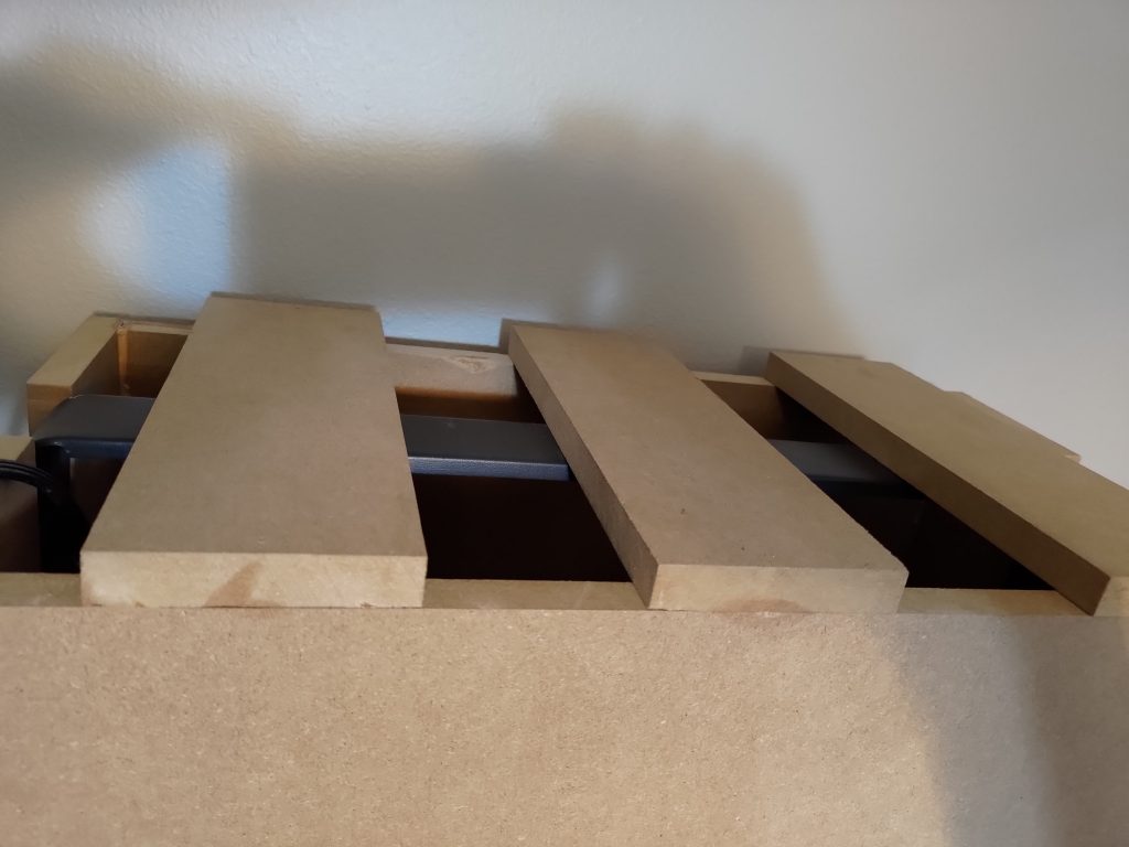
The base box is roughly 6 inches high with a surface area of 1×2 feet. This would allow me to work with anything sized 1×2 feet of course, but I also was hoping for it to be able to support 1×1 feet plastic sheets. I thought about putting an open strip in the middle of the vacuum surface, but realized that because of how the space heater is designed, it would be much better in the middle for heat distribution. This led me to cutting out two gaps about 6 inches in on each end so that I could center 1×1 plastic sheets. I did want air to pull through these strips though and I didn’t want it to leak so I picked up some silicon weather stripping and laid it down under the strips. I drilled holes through the strips and silicon so air could be pulled through in those areas. I went with silicon weather stripping because it should be able to handle the higher temps better than standard foam weather stripping. I then put inset screws into the removal strips so that I could tighten them down against the weather stripping. This gave me a nice surface for 1×2 foot pieces or I could remove the strips and use 1×1 foot sheets for smaller forms. The last step on the base box was using the silicon stripping as a seal around the entire 1×2 foot rim. I also made a couple of MDF blocks that I could screw mount over each of the outer set of air holes for when I have a 1×1 sheet mounted so that I can seal them and have suction on the smaller area.</p>

<div class="image-grid">
  <figure>
    <img src="/assets/images/wp/P_20210925_195336-1024x768.jpg" alt="" />
  </figure>
  <figure>
    <img src="/assets/images/wp/P_20210925_201822-1024x768.jpg" alt="" />
  </figure>
  <figure>
    <img src="/assets/images/wp/P_20210926_152453-1-768x1024.jpg" alt="" />
  </figure>
</div>

<p>
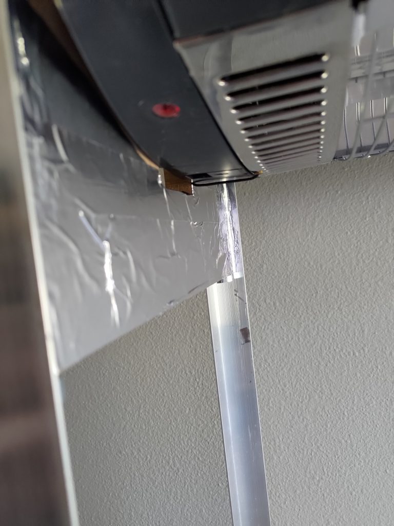
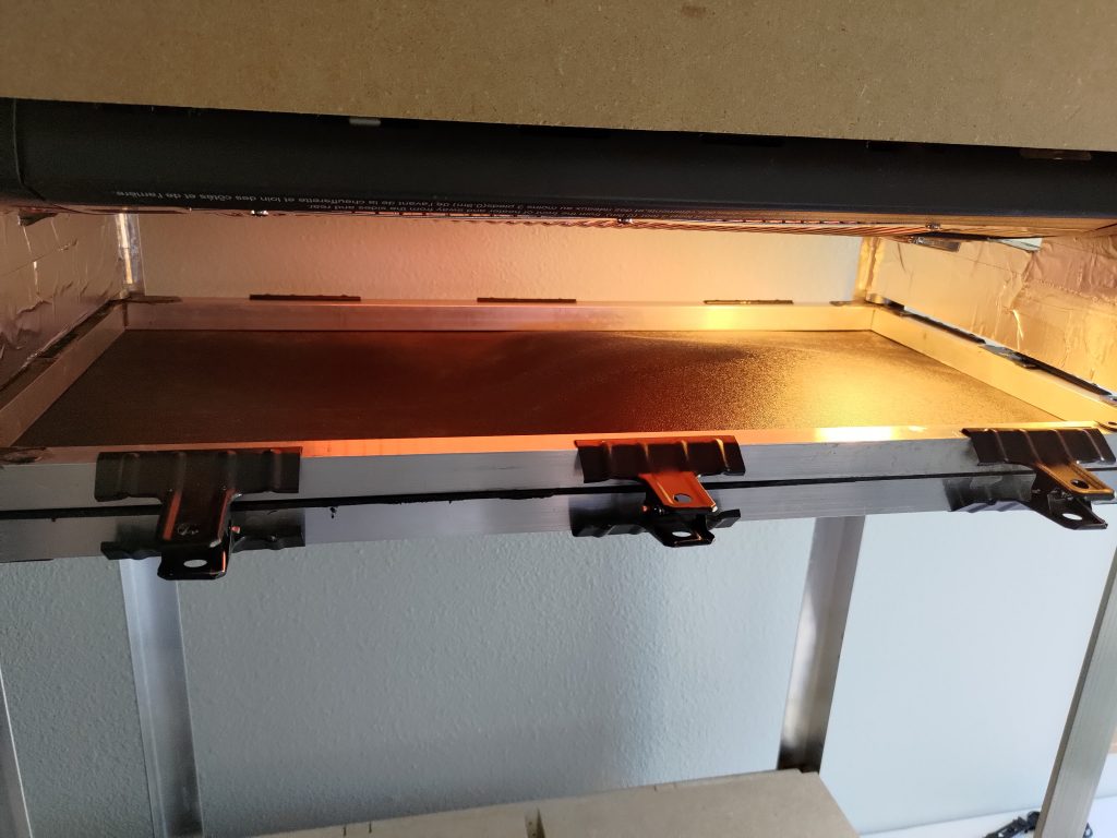
Next I built a small box to hold the heater. The heater itself is slightly larger than 1×2 foot. On the end, it is longer by the ceiling mount arms. On the sides, it is just the body itself that is longer. What I ended up doing to keep the box holding the heater to 1×2 foot, was to cut vertical holes to slide the arms into on the ends and cut the entire length of the sides slightly shorter. This meant that the ends would hang below the heater and the sides would be above the heater when the box was assembled. I used cross slats on top to provide the box with some rigidity and provide mount points for the ceiling mount arm on the heater. Since the ends hung below the heater and the vacuum former is made with MDF/plywood, I put aluminum tape on the inside to prevent burning. Lastly, I mounted the heater above the vacuum box via aluminum 90 degree lengths.</p>

<div class="image-grid">
  <figure>
    <img src="/assets/images/wp/P_20210921_091446-1-1024x768.jpg" alt="" />
  </figure>
  <figure>
    <img src="/assets/images/wp/P_20210921_091428-1-768x1024.jpg" alt="" />
  </figure>
</div>

<p>
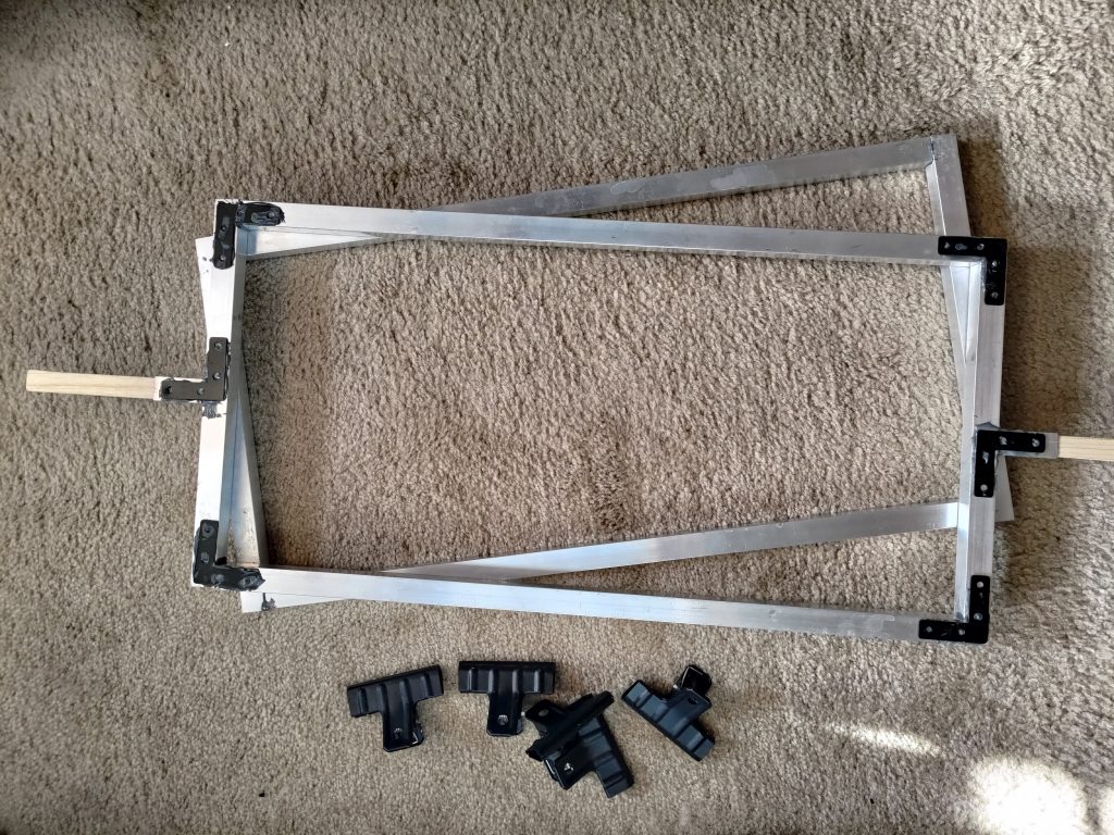
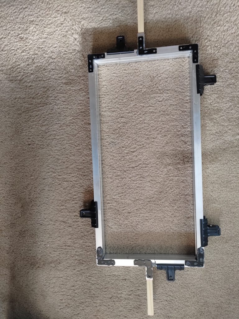
The frame that holds the plastic sheets is also made of aluminum, although this was 3/4 inch aluminum square, hollow rods. I considered a few different methods of assembling the frame, but ended up using <a href="https://www.amazon.com/J-B-Weld-8281-Professional-Reinforced/dp/B014OVHAOY/ref=sr_1_1_sspa?dchild=1&amp;keywords=jb+weld+metal&amp;qid=1632716858&amp;sr=8-1-spons&amp;psc=1&amp;spLa=ZW5jcnlwdGVkUXVhbGlmaWVyPUFOTEdDNUMzRTFWMzQmZW5jcnlwdGVkSWQ9QTA4MDY4MzgxVEFKNjBKMDFPM0ImZW5jcnlwdGVkQWRJZD1BMTAzNjc2M09IU0c2UzU4WU1VOCZ3aWRnZXROYW1lPXNwX2F0ZiZhY3Rpb249Y2xpY2tSZWRpcmVjdCZkb05vdExvZ0NsaWNrPXRydWU=">JB Weld</a> since it supported a high temp, was incredibly strong, was easy to use, and didn’t involve me getting welding equipment. In order to provide support on the corners, I used <a href="https://www.amazon.com/gp/product/B085FXRD8D/ref=ppx_yo_dt_b_search_asin_title?ie=UTF8&amp;psc=1">steel 90 degree flat brackets</a>. These didn’t have to be screwed in and I simply used the JB Weld epoxy to hold them in place. It provided a large surface area for the epoxy and thus lead to an incredibly strong joint. I used small extra pieces of aluminum rod on the ends to provide an opening that I could hammer wooden handles into so I wouldn’t have to hold onto the metal (heat resistant gloves are definitely a good idea either way). I made another frame to go below this frame with identical construction, minus the handles. The top and bottom frames were then held together by <a href="https://www.amazon.com/gp/product/B07MXVF9JY/ref=ppx_yo_dt_b_asin_title_o05_s00?ie=UTF8&amp;psc=1">steel clips</a>. I couldn’t find steel clips that would hold something this thick so I just clamped them in a vice and opened the mouth on them a bit so they would fit well. Lastly, I had to accommodate the 1×1 sheets. I made 4 pieces of aluminum rod to traverse the width of the frame and mounted a 90 degree flat bracket to each end. This allows me to clamp the pieces to the outer frame, thus providing removable inserts for 1×1 sheets.</p>

<figure>
  <img src="/assets/images/wp/P_20210925_201829-1-768x1024.jpg" alt="" />
</figure>

<p>
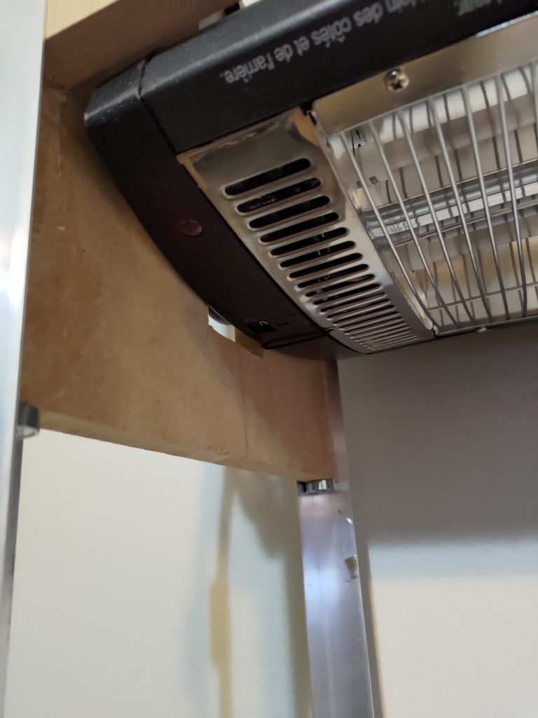
I then put magnets under each corner of the end boards on the heater box so that I could have the plastic sheet frame clamp to it while it was heating. I lubricated the vertical rails with PTFE lubricant to allow the frame to cleanly slide up and down.</p>

<p>The only other piece I needed was a shop vac. I cut a hole in the vacuum box and connected the shop vac hose to it.</p>

<figure>
  <img src="/assets/images/wp/P_20210926_154930-1-1024x768.jpg" alt="" />
</figure>

<p>And that was the build! Not an overly complicated build, but a bit of complexity added by supporting1x1 foot and 1×2 foot sheets.</p>]]></content><author><name>Michael Sgroi</name></author><category term="Plastics" /><category term="Woodworking" /><summary type="html"><![CDATA[It should be evident already from previous posts, but I do a lot of 3D printer work in my free time. Recently though, I have been trying to expand my plastics works possibilities. I’ve contemplated making a vacuum former or an injection molder. Naturally, building a vacuum former is much simpler than an injection molder so I decided to start with that. I watched quite a few YouTube videos in preparation for this build. Most of my decisions were influenced by this build video although I definitely took a different approach to some of the decisions.]]></summary><media:thumbnail xmlns:media="http://search.yahoo.com/mrss/" url="https://mcsgroi.xyz/assets/images/wp/P_20210926_154930-1-1024x768.jpg" /><media:content medium="image" url="https://mcsgroi.xyz/assets/images/wp/P_20210926_154930-1-1024x768.jpg" xmlns:media="http://search.yahoo.com/mrss/" /></entry><entry><title type="html">Maslow CNC</title><link href="https://mcsgroi.xyz/2021/05/27/maslow-cnc/" rel="alternate" type="text/html" title="Maslow CNC" /><published>2021-05-27T19:54:03-05:00</published><updated>2021-05-27T19:54:03-05:00</updated><id>https://mcsgroi.xyz/2021/05/27/maslow-cnc</id><content type="html" xml:base="https://mcsgroi.xyz/2021/05/27/maslow-cnc/"><![CDATA[<p>At the beginning of the year I purchased a Maslow CNC machine. For those who don’t know, Maslow is an open source CNC design that was developed as a lower cost alternative to some of the standard CNC machine types. It’s a really DIY machine and it took awhile to set up, but it’s finally up and running. The frame isn’t terribly difficult, but it’s definitely a two man job to put together. The biggest difficulty, though, was the firmware. We had some Z axis trouble originally. Everything would move except for Z. To remedy this, we first tried flashing different firmware variants, since one thing I’ve learned from 3D printing is that if there is a problem with an axis, it’s probably a firmware problem. At this point, the machine started acting really strange though, like moving in different directions immediately when plugged in. It turns out that EastBaySource (one of three companies who sell Maslow kits) had pivoted to using a TB6643 control board. This is not a standard board, at least not standard among most Maslow kits. The firmware that is listed on their website is modified to work on this board. This means that standard firmware, including the popular Holey firmware, is not compatible out of the box. Once we realized that this was an issue, we reverted to using the seller provided firmware. This still left the Z axis problem. I was digging through the source code when I noticed that the Z axis had a disabled option. I backtraced through the firmware and found that a Gcode command from the control computer was sending it. And that’s when it hit me – this whole issue must be because the UI on the control computer has a setting to disable the Z axis. I went digging through the settings and, sure enough, found that the Z axis was disabled by default. No idea why that would be the case, but here it was. I also found out that the EastBaySource version of GroundControl (the UI for controlling Maslow) had the Z axis enabled by default. Since I was using WebControl (a newer UI for controlling Maslow) that I pulled from another site, it wasn’t enabled by default. Turned that on and it all started working.</p>

<p>All in all, I’m very impressed with the machine. The design is pretty great. It has a smaller footprint than tabletop CNC machines so you can fit it in a smaller area and the cost is significantly lower. It is VERY DIY though. So if you are looking for something to “just work” straight out of the box, you will be disappointed. There are also a few shortcomings in the original schematics. The biggest one is the ability to CNC around the edges of the board you are cutting. It can’t handle close to the left, right, and bottom edges very well. I’ve seen some great ideas to solve this online though and this is probably where I’ll head next.</p>

<div class="image-grid">
  <figure>
    <img src="/assets/images/wp/20210526_183143-scaled.jpg" alt="" />
  </figure>
  <figure>
    <img src="/assets/images/wp/20210526_182908-768x1024.jpg" alt="" />
  </figure>
</div>

<p>The other upgrade that I would suggest is using WebControl instead of GroundControl for managing the CNC machine. GroundControl has to be on a laptop, whereas WebControl could be loaded onto a RaspberryPi and remotely controlled since it hosts a website. I ended up balancing the onsite control with remote control by using WebControl, but putting it on a laptop so that I can control it onsite easily, but also monitor it remotely and upload Gcode from my desktop similar to OctoPrint or Repetier Server. The last task I had to solve, was to find a place to put an old laptop out in my garage. I ended up making a small laptop stand, which also gave me a chance to practice with pocket holes 🙂</p>]]></content><author><name>Michael Sgroi</name></author><category term="CNC" /><category term="Woodworking" /><summary type="html"><![CDATA[At the beginning of the year I purchased a Maslow CNC machine. For those who don’t know, Maslow is an open source CNC design that was developed as a lower cost alternative to some of the standard CNC machine types. It’s a really DIY machine and it took awhile to set up, but it’s finally up and running. The frame isn’t terribly difficult, but it’s definitely a two man job to put together. The biggest difficulty, though, was the firmware. We had some Z axis trouble originally. Everything would move except for Z. To remedy this, we first tried flashing different firmware variants, since one thing I’ve learned from 3D printing is that if there is a problem with an axis, it’s probably a firmware problem. At this point, the machine started acting really strange though, like moving in different directions immediately when plugged in. It turns out that EastBaySource (one of three companies who sell Maslow kits) had pivoted to using a TB6643 control board. This is not a standard board, at least not standard among most Maslow kits. The firmware that is listed on their website is modified to work on this board. This means that standard firmware, including the popular Holey firmware, is not compatible out of the box. Once we realized that this was an issue, we reverted to using the seller provided firmware. This still left the Z axis problem. I was digging through the source code when I noticed that the Z axis had a disabled option. I backtraced through the firmware and found that a Gcode command from the control computer was sending it. And that’s when it hit me – this whole issue must be because the UI on the control computer has a setting to disable the Z axis. I went digging through the settings and, sure enough, found that the Z axis was disabled by default. No idea why that would be the case, but here it was. I also found out that the EastBaySource version of GroundControl (the UI for controlling Maslow) had the Z axis enabled by default. Since I was using WebControl (a newer UI for controlling Maslow) that I pulled from another site, it wasn’t enabled by default. Turned that on and it all started working.]]></summary><media:thumbnail xmlns:media="http://search.yahoo.com/mrss/" url="https://mcsgroi.xyz/assets/images/wp/20210523_185719-1024x768.jpg" /><media:content medium="image" url="https://mcsgroi.xyz/assets/images/wp/20210523_185719-1024x768.jpg" xmlns:media="http://search.yahoo.com/mrss/" /></entry><entry><title type="html">FrankenSnappy</title><link href="https://mcsgroi.xyz/2021/05/05/frankensnappy/" rel="alternate" type="text/html" title="FrankenSnappy" /><published>2021-05-05T22:17:57-05:00</published><updated>2021-05-05T22:17:57-05:00</updated><id>https://mcsgroi.xyz/2021/05/05/frankensnappy</id><content type="html" xml:base="https://mcsgroi.xyz/2021/05/05/frankensnappy/"><![CDATA[<p>I had been looking for a larger volume FDM printer for awhile. I know there are a few on the market, but they tend to get fairly expensive and there are some still some pretty definite caps on size (unless you are planning on a business grade printer).</p>

<p>Well I had waffled on a larger printer for awhile for the reasons I mentioned and just couldn’t decide on one I liked. That’s when I saw this project called <a href="https://github.com/revarbat/snappy-reprap/wiki/v3.0-Home">Snappy</a> listed as a RepRap project. For those who don’t know, RepRap is a collaborative initiative to make 3d printers accessible. It has resulted in some really great open source designs.</p>

<p>The Snappy was designed as an almost entirely 3d printed 3d printer. The great thing about this concept is that it’s relatively scalable. All the parts snap together (as the name implies), so you can increase all three dimensions by simply adding more snap together parts, at least theoretically.</p>

<p>What I found out part way through piecing this concept together, was that there were some design choices that meant this printer was fairly locked in at the size it was designed at. For instance, the gantry was angled so that it peaked in the middle where the hot end hangs. This means that adding more gantry pieces to make it wider would lift the hot end too high. Another problem was that a larger bed would put too much weight on the edges of the floating Y axis resulting in the printer tipping and the snap together parts starting to give.</p>

<figure>
  <img src="/assets/images/wp/20210505_210449_HDR-1-1024x1024.jpg" alt="" />
</figure>

<p>These fixes and a few improvements led to the FrankenSnappy. It has a 1 ft. square bed and can print objects a little over a foot high. I also added an E3D hot end which is a significant improvement over the J head hot end that it was originally designed with. It also uses an aluminum backed heated bed with a magnetic PEI sheet.</p>

<p>There are still some small improvements that could be made, but I’m fairly happy with it. It works pretty well and can do exactly what I designed it for – print large objects. The designs for this can be found on <a href="https://www.thingiverse.com/thing:4571980">Thingiverse</a>.</p>]]></content><author><name>Michael Sgroi</name></author><category term="3D Printing" /><summary type="html"><![CDATA[I had been looking for a larger volume FDM printer for awhile. I know there are a few on the market, but they tend to get fairly expensive and there are some still some pretty definite caps on size (unless you are planning on a business grade printer).]]></summary><media:thumbnail xmlns:media="http://search.yahoo.com/mrss/" url="https://mcsgroi.xyz/assets/images/wp/20210505_210449_HDR-1-1024x1024.jpg" /><media:content medium="image" url="https://mcsgroi.xyz/assets/images/wp/20210505_210449_HDR-1-1024x1024.jpg" xmlns:media="http://search.yahoo.com/mrss/" /></entry><entry><title type="html">EnderLoop</title><link href="https://mcsgroi.xyz/2021/03/27/enderloop/" rel="alternate" type="text/html" title="EnderLoop" /><published>2021-03-27T23:49:23-05:00</published><updated>2021-03-27T23:49:23-05:00</updated><id>https://mcsgroi.xyz/2021/03/27/enderloop</id><content type="html" xml:base="https://mcsgroi.xyz/2021/03/27/enderloop/"><![CDATA[<p>This is one of my most recent projects. I had been doing research on conveyor belt 3d printers and realized that all of the options were way too expensive. I realized that this just wasn’t approachable for common users. To that end I started down the path of modding an Ender 3 printer to turn it into a belt printer.</p>

<p>Utilizing an Ender 3 provides a couple main benefits. The first is that the mod is very cost effective. An Ender 3 can be purchased for $200 (and that’s before considering sales/discounts) and the mod ends up costing between $100-$250 depending on what parts you have on hand. The second is that this printer already supports a large number of pre-existing mods by nature of it utilizing an Ender 3. Many of the same mods you would want on your Ender 3 should be compatible here or at least require minimal changes.</p>

<h2 id="development">Development</h2>

<p>I’ve made a couple of major iterations on this project now. The first version worked, but had a few issues:</p>

<figure>
  <img src="/assets/images/wp/EnderLoopV1.jpg" alt="" />
  <figcaption>EnderLoop V1</figcaption>
</figure>

<ol>
  <li>Belt surface was warped and uneven. Part of this was just poor craftsmanship on my part when laying down Kapton tape for the belt. That said, I was really hoping for a better belt option</li>
  <li>Parts come off the machine elongated a bit. This was a combination of a few things. Esteps, improper part cooling, and gantry angle all contributed to this.</li>
  <li>The belt was curving the model print a bit. The issue was that the hot end mount wasn’t tall enough since I used the standard one on the Ender 3. This resulted in having to print material too close to the curve on the roller.</li>
</ol>

<p>These issues led me to release the V2 designs which are now out in the wild. While not perfect, they are a huge improvement over the V1 designs and have resulted in a fully functional belt printer. A few key changes made a massive improvement. There were obviously some small firmware tweaks required, but the really consequential changes were:</p>

<figure>
  <img src="/assets/images/wp/overview2-768x1024.jpg" alt="" />
  <figcaption>EnderLoop V2</figcaption>
</figure>

<ol>
  <li>Partnering with Adam at PowerBelt for a cost effective belt for the printer. He hosts a custom sized belt for anyone who wants to make this themselves (link is in the instructions). This is a PET surface that provides better adhesion than the Kapton design from my previous iteration and the backing material grips the rollers much better.</li>
  <li>Improving the part cooling fan duct. This helped direct the airflow much more appropriately resulting in better material cooling.</li>
  <li>Designing gantry supports allowed for a sturdier printer and helped ensure an accurate 45 degree angle on the gantry.</li>
  <li>Vertically elongating the hot end allowed for the printer to lay material down further in on the belt. This resulted in a flat surface on the bottom of the model, removing the previous curvature issue.</li>
</ol>

<h2 id="results">Results</h2>

<p>The final designs ended up yielding some positive prints. I printed out a few test models here: CaliCat, Benchy, and an Articulate Chameleon. These designs can all be found on Thingiverse and are all fairly tricky prints for 3d printers to handle.</p>

<div class="image-grid">
  <figure>
    <img src="/assets/images/wp/calicat2-1-700x1024.jpg" alt="" />
    <figcaption>CaliCat</figcaption>
  </figure>
  <figure>
    <img src="/assets/images/wp/chameleon1-1024x768.jpg" alt="" />
    <figcaption>Articulated Chameleon</figcaption>
  </figure>
  <figure>
    <img src="/assets/images/wp/benchycomp2-1024x768.jpg" alt="" />
    <figcaption>The Benchy on the left is from the EnderLoop and the Benchy on the right is from a CR-6 SE for reference.</figcaption>
  </figure>
</div>

<h2 id="tldr">TLDR</h2>

<p>While this is similar to the CR-30, this mod costs about 1/3-1/2 of the price (including the cost of an Ender 3), offers more mod flexibility since the core mechanics are those of the Ender 3 which already has a plethora of mods available online, and is available right now. Also, since the support extensions are 3d printed, you can cheaply and effectively add longer support than other belt printers available. The tradeoffs are that it is a bit slower than the CR-30 and requires some DIY know-how with printers.</p>

<p>All things considered, this is a fairly simple and cost effective means of obtaining a belt printer as an alternative to some of the <a href="https://all3dp.com/2/3d-printer-belt-all-you-need-to-know/">available ones on the market</a>.</p>

<p>I’ve got it hosted on <a href="https://www.thingiverse.com/thing:4658201">Thingiverse</a> and <a href="https://github.com/mcsgroi/EnderLoop">Github</a>. There’s also an Instructable for it <a href="https://www.instructables.com/EnderLoop/">here</a>.</p>

<p>There are a couple great YouTube resources for learning more available <a href="https://www.youtube.com/watch?v=L337KpcwrPk&amp;feature=youtu.be">here</a> and <a href="https://youtu.be/P7elE_QoYi8">here</a>. It’s also been featured in a Hackaday article <a href="https://hackaday.com/2021/02/25/turn-an-ender-3-into-a-belt-3d-printer-of-your-very-own/">here</a> and in the best conveyor belt printer designs on 3dWithUs <a href="https://3dwithus.com/conveyor-belt-3d-printers">here</a>.</p>

<p>It’s also won an award in the Creality Global DIY contest (<a href="https://www.creality.com/blog-detail/creality-diy-global-creative-contest">article</a>, <a href="https://youtu.be/NsFzNNXlL6A">video</a>). And it’s been featured Instructables and was a runner up in their <a href="https://www.instructables.com/contest/cnc2021/">2021 CNC contest</a>.</p>]]></content><author><name>Michael Sgroi</name></author><category term="3D Printing" /><summary type="html"><![CDATA[This is one of my most recent projects. I had been doing research on conveyor belt 3d printers and realized that all of the options were way too expensive. I realized that this just wasn’t approachable for common users. To that end I started down the path of modding an Ender 3 printer to turn it into a belt printer.]]></summary><media:thumbnail xmlns:media="http://search.yahoo.com/mrss/" url="https://mcsgroi.xyz/assets/images/wp/EnderLoopV1.jpg" /><media:content medium="image" url="https://mcsgroi.xyz/assets/images/wp/EnderLoopV1.jpg" xmlns:media="http://search.yahoo.com/mrss/" /></entry></feed>